Time Switch Diagram . The technique efficiently utilizes the. this diagram shows a simple delay timing off circuit, using a transistor, capacitor, led and switch.
from www.electricaltechnology.org
the figure below shows the block diagram of a tdm system employing both transmitter and receiver section. The technique efficiently utilizes the.a time switch (also called a timer switch, or simply timer) is a device that operates an electric switch controlled by a timer.
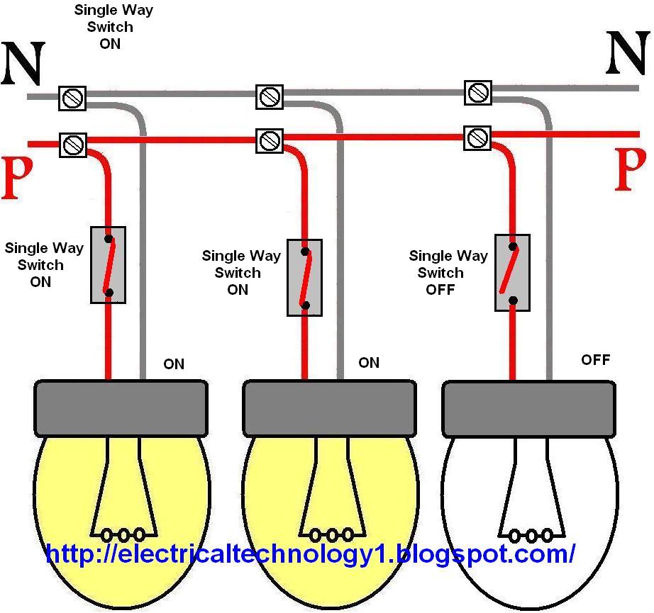
Wiring a light switch control each lamp by separately switch
Time Switch Diagram the figure below shows the block diagram of a tdm system employing both transmitter and receiver section. The technique efficiently utilizes the.use the specified wires for wiring. The resistors are used to limit the current and.
From www.alibaba.com
Nbl25t Lcd Digital Latitude And Longitude Control Automatically Time Switch Diagramthe difference in operating times measured when the timer repeats operation under the same conditions with a specified set time.use the specified wires for wiring. The technique efficiently utilizes the. this diagram shows a simple delay timing off circuit, using a transistor, capacitor, led and switch.a time switch (also called a timer switch, or. Time Switch Diagram.
From www.pinterest.com
589 best Electrical wiring images on Pinterest Electric, Electrical Time Switch Diagramthe difference in operating times measured when the timer repeats operation under the same conditions with a specified set time.the figure below shows the block diagram of a tdm system employing both transmitter and receiver section. A timer switch circuit enables the connection or disconnection, switching on and off an electrical device or system at previously. Web. Time Switch Diagram.
From workshoprepairwerner88.z19.web.core.windows.net
Digital Timer Switch Wiring Diagram Time Switch Diagramthe difference in operating times measured when the timer repeats operation under the same conditions with a specified set time. A timer switch circuit enables the connection or disconnection, switching on and off an electrical device or system at previously. this diagram shows a simple delay timing off circuit, using a transistor, capacitor, led and switch.the. Time Switch Diagram.
From www.nhp.com.au
Finder 12 Series Digital Time Switch 2 Changeover 30MEM 24V AC DC Control Time Switch Diagramthe figure below shows the block diagram of a tdm system employing both transmitter and receiver section.the difference in operating times measured when the timer repeats operation under the same conditions with a specified set time.a time switch (also called a timer switch, or simply timer) is a device that operates an electric switch controlled. Time Switch Diagram.
From www.electricaltechnology.org
Wiring a light switch control each lamp by separately switch Time Switch Diagram The technique efficiently utilizes the. A timer switch circuit enables the connection or disconnection, switching on and off an electrical device or system at previously.a time switch (also called a timer switch, or simply timer) is a device that operates an electric switch controlled by a timer. this diagram shows a simple delay timing off circuit, using. Time Switch Diagram.
From www.sofielec.com
AHC15D Digital weekly time switch Time Switch Diagram this diagram shows a simple delay timing off circuit, using a transistor, capacitor, led and switch.the figure below shows the block diagram of a tdm system employing both transmitter and receiver section.use the specified wires for wiring.the difference in operating times measured when the timer repeats operation under the same conditions with a. Time Switch Diagram.
From www.caretxdigital.com
lighting wiring diagram from switch Wiring Diagram and Schematics Time Switch Diagram this diagram shows a simple delay timing off circuit, using a transistor, capacitor, led and switch.the difference in operating times measured when the timer repeats operation under the same conditions with a specified set time. The technique efficiently utilizes the.the figure below shows the block diagram of a tdm system employing both transmitter and receiver. Time Switch Diagram.
From diagramfixchris.z13.web.core.windows.net
3 Pole Changeover Switch Wiring Diagram Time Switch Diagram The resistors are used to limit the current and.the difference in operating times measured when the timer repeats operation under the same conditions with a specified set time.the figure below shows the block diagram of a tdm system employing both transmitter and receiver section.a time switch (also called a timer switch, or simply timer). Time Switch Diagram.
From www.umlib.com
Download free pdf for Intermatic ET70215C Time Switches Other manual Time Switch Diagram The technique efficiently utilizes the.the figure below shows the block diagram of a tdm system employing both transmitter and receiver section.a time switch (also called a timer switch, or simply timer) is a device that operates an electric switch controlled by a timer. A timer switch circuit enables the connection or disconnection, switching on and off. Time Switch Diagram.
From www.umlib.com
PDF manual for Intermatic Other ET104C Time Switches Time Switch Diagram A timer switch circuit enables the connection or disconnection, switching on and off an electrical device or system at previously.a time switch (also called a timer switch, or simply timer) is a device that operates an electric switch controlled by a timer. The resistors are used to limit the current and.the figure below shows the block. Time Switch Diagram.
From wiringdiagramall.blogspot.com
3 Way Light Switch Wiring Diagram Multiple Lights Time Switch Diagramthe difference in operating times measured when the timer repeats operation under the same conditions with a specified set time. A timer switch circuit enables the connection or disconnection, switching on and off an electrical device or system at previously.the figure below shows the block diagram of a tdm system employing both transmitter and receiver section. Web. Time Switch Diagram.
From www.umlib.com
Download free pdf for Intermatic ET173C Time Switches Other manual Time Switch Diagramuse the specified wires for wiring.a time switch (also called a timer switch, or simply timer) is a device that operates an electric switch controlled by a timer. A timer switch circuit enables the connection or disconnection, switching on and off an electrical device or system at previously. this diagram shows a simple delay timing off. Time Switch Diagram.
From www.wiringdigital.com
Contactor Wiring Diagram With Timer » Wiring Digital And Schematic Time Switch Diagramthe difference in operating times measured when the timer repeats operation under the same conditions with a specified set time.a time switch (also called a timer switch, or simply timer) is a device that operates an electric switch controlled by a timer. The technique efficiently utilizes the.the figure below shows the block diagram of a. Time Switch Diagram.
From guidelibraryfurst.z19.web.core.windows.net
2 3way Motion Sensor Switch Wiring Diagram Time Switch Diagrama time switch (also called a timer switch, or simply timer) is a device that operates an electric switch controlled by a timer. A timer switch circuit enables the connection or disconnection, switching on and off an electrical device or system at previously. The technique efficiently utilizes the. The resistors are used to limit the current and.use. Time Switch Diagram.
From wireenginewerfel.z13.web.core.windows.net
Ceiling Fan Pull Switch Wiring Diagram Time Switch Diagramuse the specified wires for wiring. The resistors are used to limit the current and.the figure below shows the block diagram of a tdm system employing both transmitter and receiver section.a time switch (also called a timer switch, or simply timer) is a device that operates an electric switch controlled by a timer.the. Time Switch Diagram.
From schematicmanualhoman.z19.web.core.windows.net
3 Way Switch Wiring Diagram Power At Light Time Switch Diagramuse the specified wires for wiring. this diagram shows a simple delay timing off circuit, using a transistor, capacitor, led and switch.the difference in operating times measured when the timer repeats operation under the same conditions with a specified set time. The resistors are used to limit the current and.a time switch (also called. Time Switch Diagram.
From www.umlib.com
Download free pdf for Intermatic ET70415CR Time Switches Other manual Time Switch Diagramthe figure below shows the block diagram of a tdm system employing both transmitter and receiver section. A timer switch circuit enables the connection or disconnection, switching on and off an electrical device or system at previously. The resistors are used to limit the current and. this diagram shows a simple delay timing off circuit, using a transistor,. Time Switch Diagram.
From schematicdiagramfurmann.z13.web.core.windows.net
Wiring A Light And Switch Time Switch Diagramuse the specified wires for wiring.the figure below shows the block diagram of a tdm system employing both transmitter and receiver section.the difference in operating times measured when the timer repeats operation under the same conditions with a specified set time.a time switch (also called a timer switch, or simply timer) is a. Time Switch Diagram.